Introduction
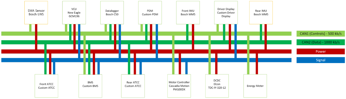
This is a summary based off the slides I presented at MIS 2026 Design, I go over our electrical/CAN architecture, as well as wiring harness design and manufacturing.
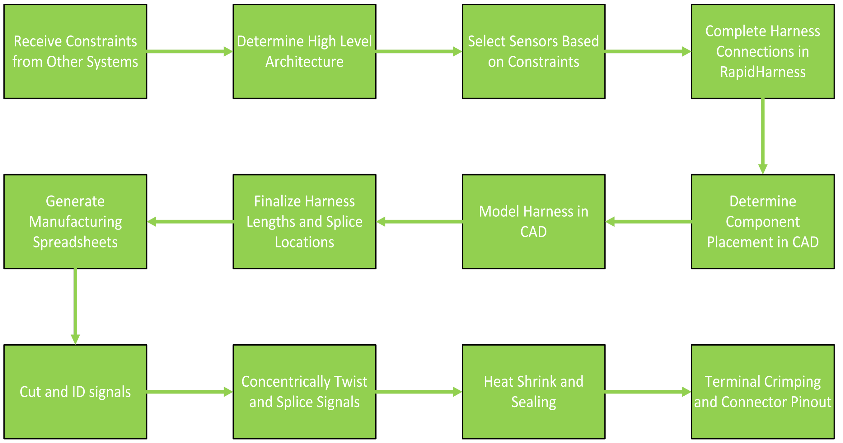
This was the harness design and manufacturing proccess I had done for SR26's harness. This proccess allowed flexibility in the SR26 vehicle design by approaching the harness as a system constrained by other systems.
Overview
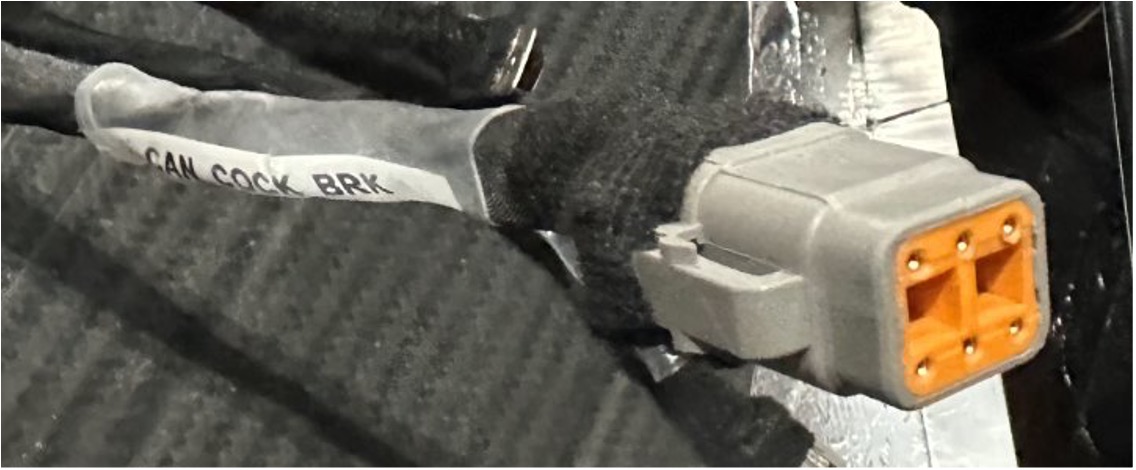
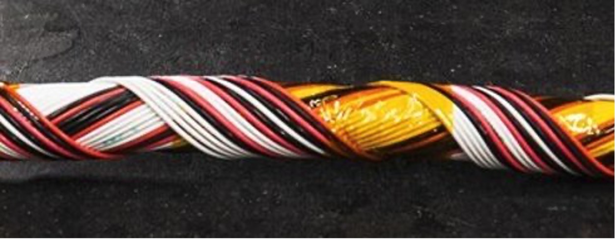
This is a motorsport-spec wiring harness, utilizing concentric twisting to ensure flexibility for tight packaging constraints. It's fully sealed with heat shrink to avoid unwanted elements.
The main harness is split into several sub harnesses. The ones I had lead were the Main harness's front and rear harness, as well as the charging harness.
Connectors and Contact Selection
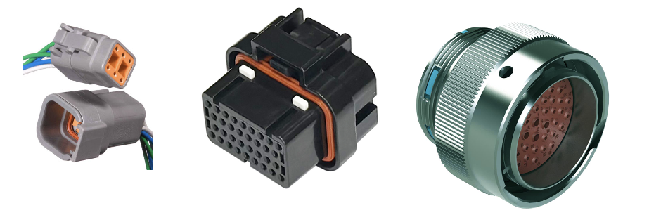
The main considerations were price, contact size, number of contacts, current rating, environmental seal, and temperature rating. We chose deutsch autosport for cases where we had a large # of contacts and wanted a small connector, and chose deutsch dt for general purpose connections such as pigtails and breakouts.
We use TE and Ampseal connectors for our custom modules, Molex and JST are used for small connections within the tractive system container. We use Amphenol bulkheads for our panel mount connectors.
Electrical and Harness CAD
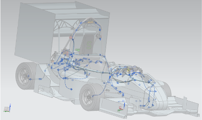
I had collaborated with electronics, powertrain, and mechanical teams working on the CAD. The proccess started with having mechanical and powertrain space reservation done in CAD so I could start deciding how electronics would be placed.
In the rear of the car, electronics placements was trying to keep modules close together, and also placed in a way to make harness routing as easy as possible.
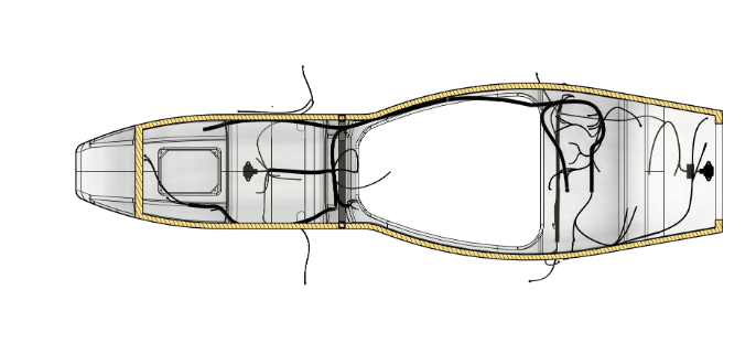
The main design based around placement is we have an Analog to Can Converter (ATCC) module in both the front and rear to reduce sensor wire length and overall reduce noise as best we can.
Main Harness Schematic
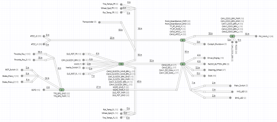
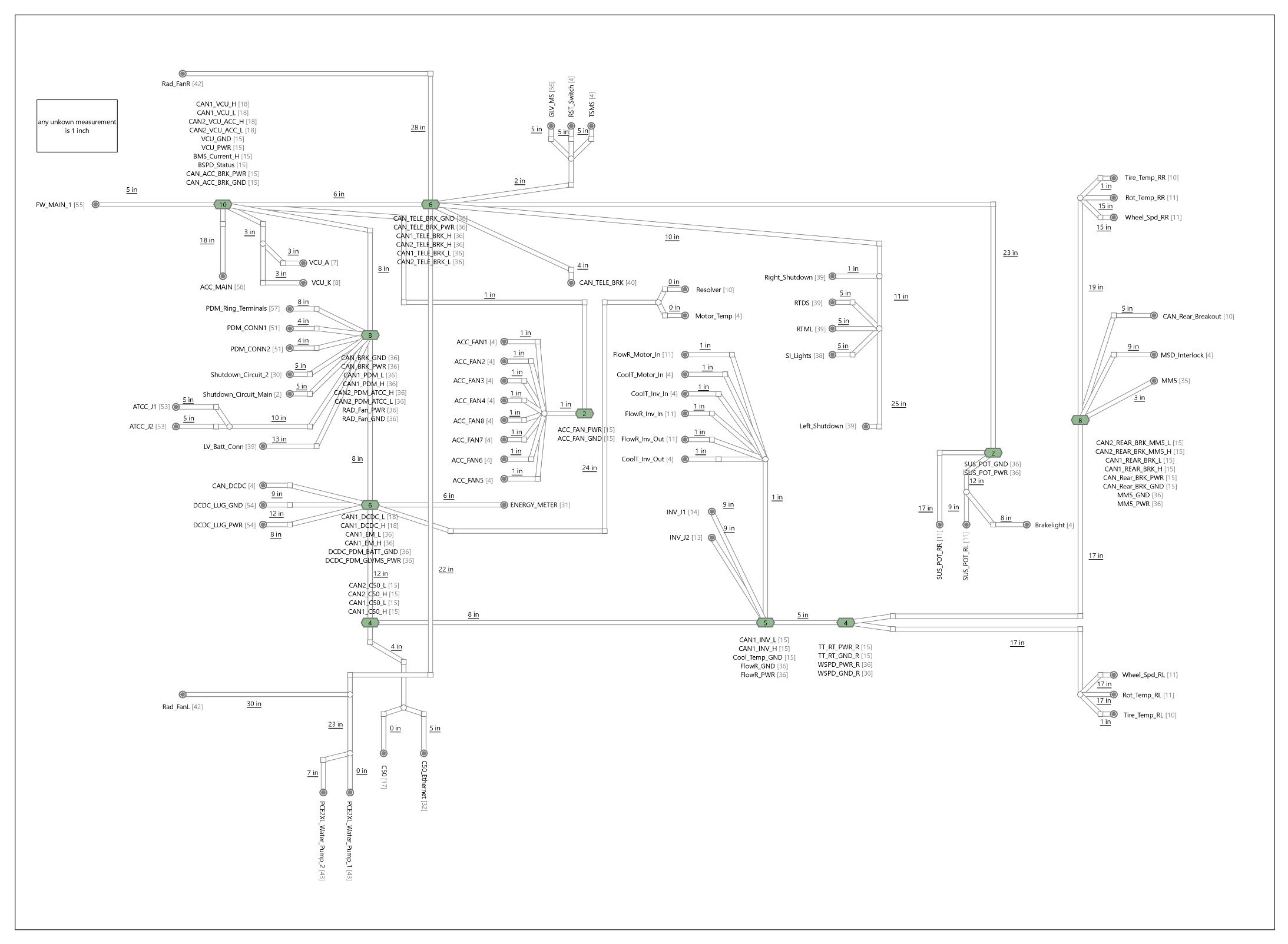
The front and rear harness schematic is shown below, the main point is that I had used a nonlinear harness design to fully utilize packaging constraints.
Charging Harness
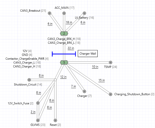
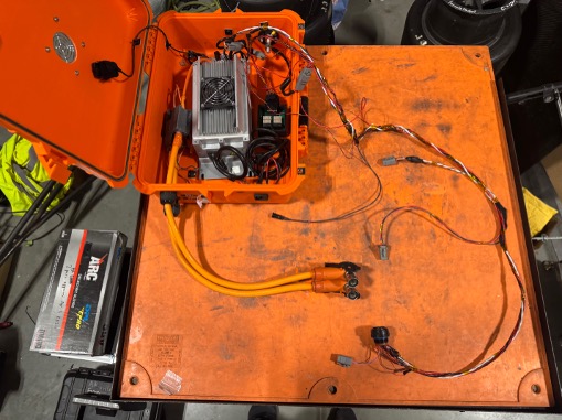
Below is the charging harness schematic and the manufactured version. The CAN breakouts by the tractive system container connector allow us to moniter the state of charging.
Manufacturing Sheets and Wire ID's
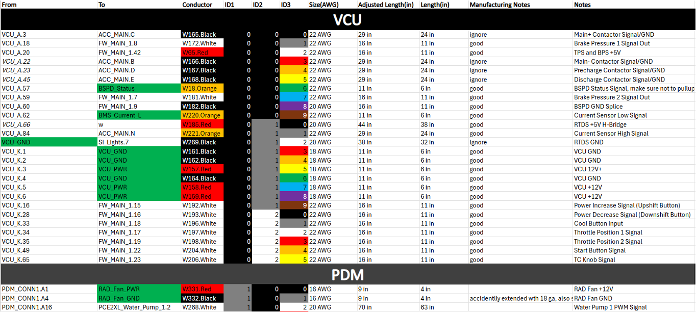
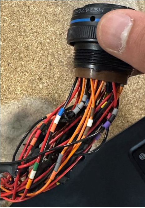
Excel Manufacturing sheets allow use to track the state of manufacturing. We use corresponding wire ID's to track wires allowing easy diagnosis.
Manufacturing Process
Concentric Twisting shown below, allows for flexibility within tight packaging.
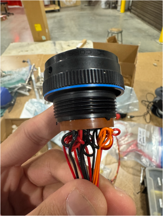
Service Loops were done as well to minimize tension of the connectors and prevent contacts from pulling out.
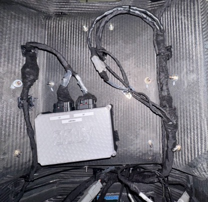
Harness Protection
Raychem DR-25 heat shrink, chosen for abrasion resistance and full sealing, used within the main harness extensively.
Raychem SCL used for sealing connectors as an alternative to connector boots.
Raychem ATUM used for tension relief in crimp splices.
Tesa Tape used as an alternative to DR-25 to cover the harness back up after opening it, if a connection had to be serviced.
Wire Selection
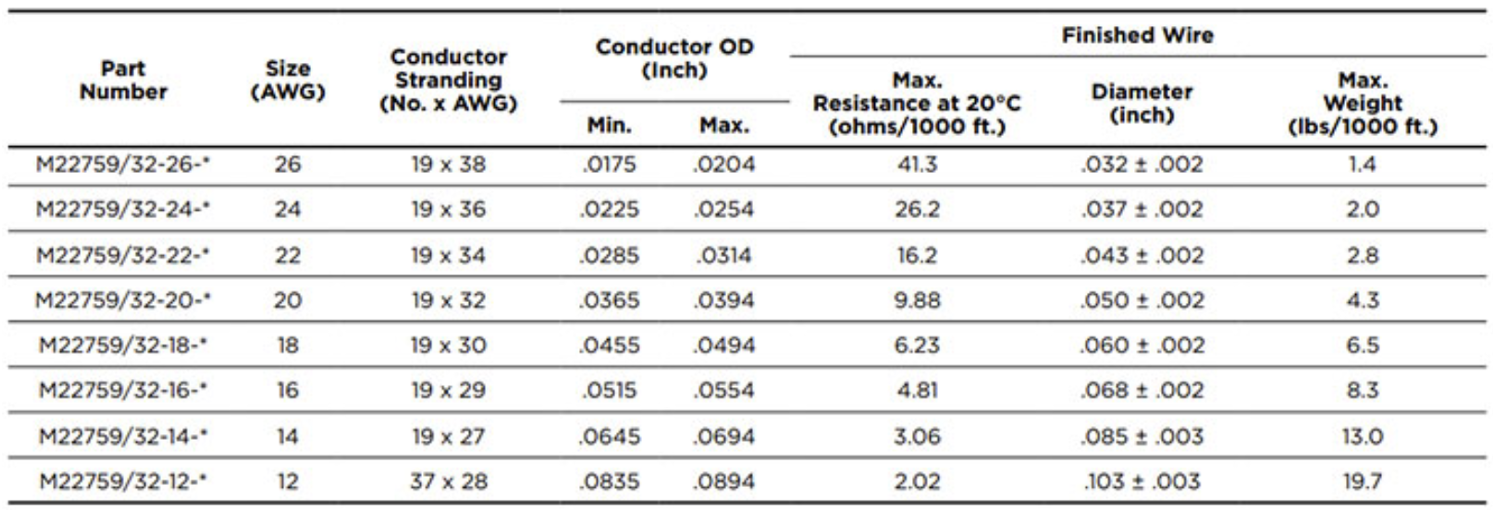
Milspec 22759/32 has a cross linked ETFE casing. We chose this wire because of its high ratings, and has a higher cross sectional area for the same gauge allowing lower impedance losses, and a higher ability to carry more current.
Wire Sizing
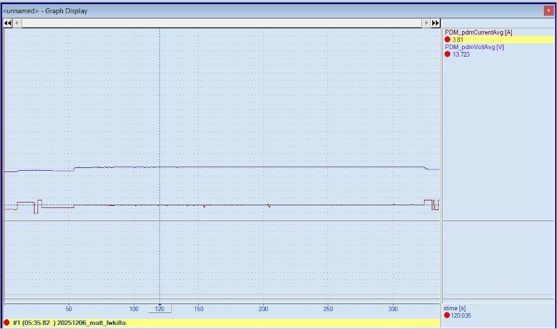
Wire Sizing based on both datasheets and data logs, this allowed us to maximize wire gauges, and allowed us to opt for more splicing, cutting several connectors and even a bulhead.
Wire Length Estimation
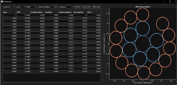
Wire Lengths were based on a simulation model I built within MATLAB, I modeled concetric harness wiring similarly to a twisted rope using some basic geometry calculations.
This also allowed us to see the packing of our wiress, redbull racing has a good chart explaining wire packing in concentric twisting but the issue is that it is for wires of the same gauge and in our harness, it is not something we have, so I wanted to model that as well.
I ended up on the MATLAB Students instagram page where I explained this. https://www.instagram.com/reel/DcGcw-qmYWM/?utm_source=ig_web_copy_link&igsi=MzRlODBiNWFlZA==
Results
- Firewall Bulkhead Reduction allowing us to fully sit the harness within the chassis to be un-noticable to the driver
- Passed all FSAE electrical tech inspection requirements
- "Best harness our MIS judge has seen"
Future optimizations
The main thing to optimize in the future is reducing long wires for any power signal, this year we found noticable impedance (3 ohms) within our High Voltage Interlock line that caused a 1-2V drop in voltage in steady state.